
Introduction and Measuring Principle
Flowmasonic WUF 620 transit-time ultrasonic flow meter utilizes the transit-time principle, including clamp-on and insertion. When installing a clamp-on transducer, without flow stop and pipe cutting, simple installation and convenient for online comparison. Different sizes of transducers can measure different sizes‟ of pipe. Insertion installation effectively solves clap-on flow meter can not accurately measure with scaling pipe and non-conductive media. Insertion transducer has a stop ball valve, without flow stop or pipe cut, easy to install.
 |
| Flowmasonic WUF 620 CF Clamp-On Ultrasonic Flowmeter |
Users also can mount hoops on the unweldable pipe surface. Optional thermal energy measuring function. Widely applied in processing monitoring, water balance test, district heating balance test, energy efficiency monitoring, etc.
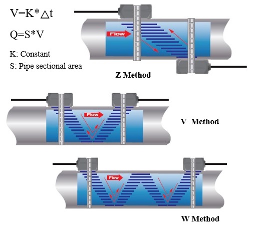
Flowmasonic WUF 620 Transit-time ultrasonic flow meter utilizes the difference of ultrasonic pulse forwarding and reversing flow rate to measure flow. Use a pair of transducers to transmit and receive signals alternately. The Transducer signal travels faster downstream than upstream. Obtain transit-time △t by measuring signal travel time in downstream and upstream, the average flow velocity can be detained according to △t and velocity V. The volume flow Q can be calculated out of the flow velocity V and pipe profile S.
Flowma Flowmasonic WUF 620 CF Clamp-on transit-time ultrasonic flow meter utilizes the transit-time principle. The Flowmasonic transducer is mounted outside the surface of the pipe without requirements of flow stop or pipe cutting. It’s very simple and convenient for installation, calibration, and maintenance.
Different sizes of transducers satisfy different measuring demands. Plus, select the thermal energy measuring function to achieve complete energy analysis. It is widely applied in processing monitoring, water balance test, district heating balance test, and energy efficiency monitoring as easy installation and simple operation advantages.
Application
- Water Utility
- Water Conservancy & Resource
- College & University
- HVAC
- Manufacturing
- Draining Company
- Heating Supply Industry
- Petrochemical Industry
Flowma Flowmasonic WUF 620 CF Series Features
- 4 Lines Display Velocity, Flow Rate, Volume, And Meter Status
- Clamp-on Mounted, Unnecessary Pipe Cutting Or Processing Interruption
- Acceptable Fluid Temperature Range -40°C~260°C
- Built-in Data Storage Is Optional
- Selecting Temperature Sensor PT1000 To Achieve Thermal Energy Measurement Function
- Suitable For DN20-DN6000 Flow Measurement By Selecting Different Size Transducers
- The insertion flow meter is suitable for measuring the DN65-6000 pipeline flow
- Bi-directional measurement, flow range from 0.01m/s to 12m/s
- Available for transducers with waterproof or ip68 class
- Available dual power supply 220 VAC and 24 VDC
Specification of WUF 620 CF

Ultrasonic Transmitter Flowmasonic WUF 620 CF
- Measuring Principle Transit-time
- Velocity 0.01 - 12 m/s, Bi-directional measurement
- Resolution 0.25mm/s
- Repeatability 0.2%
- Accuracy ±1.0% R
- Response Time 0.5s
- Sensitivity 0.003m/s
- Damping 0-99s(settable by user )
- Suitable Fluid Clean or tiny amounts of solids, air bubbles liquid, Turbidity <10000 ppm
- Power Supply AC: 85-265V DC:12- 36V/500mA
- Installation Wall Mounted
- Protection Class IP66
- Operating Temperature -40℃ -75℃
- Enclosure Material Fiberglass
- Display 4X8 Chinese Or 4X16 English, Backlit
- Measuring Unit Meter, Ft, m³, liter, ft³, gallon, barrel, etc.
- Communication Output 4~20mA, OCT, Relay, RS485 (Modbus-RUT), Date Logger, GPRS
- Energy Measuring Unit Unit: GJ, Opt: KWh
- Security Keypad Lockout, System Lockout
- Size 244*196*114(mm)
- Weight 3kg
Ultrasonic Transducer WUF 620 CF
- Protection Class IP67 ( Optional to IP 68 )
- Fluid Temperature
- Std. transducer -40℃~85℃(Max.120℃)
- High Temp -40℃~260℃
- Pipe Size 20mm~6000mm
- Transducer Size
- S (20mm~50mm)
- M (40mm~1000mm)
- L (1000mm~6000mm)
- Transducer Material Std. Aluminum alloy, High Temp.(PEEK)
- Temperature Sensor PT1000
- Cable Length Std. 10m (customized)
Pipe material
The window for selecting pipe material, familiar pipe materials include:
(The materials must be equable, compact, and can transmit ultrasound)
- .Carbon steel
- PVC
- Stainless steel
- Aluminum
- Cast iron
- Asbestos
- Ductile iron
- Fiberglass
- Copper
- Others
Fluid Type
This ultrasonic flow meter WUF 620 CF can be used for the following types of homogeneous liquids :
- Water
- Sea Water
- Diesel Oil
- Kerosene
- .Castor Oil
- Gasoline
- Peanut Oil
- Fuel oil
- Gasoline #90
- Crude Oil
- Gasoline #93
- Propane at -45℃
- Alcohol
- Butane(0℃)
- Water(125℃)
- Other
Flow unit selection
The Ultrasonic low meter WUF 620 CF has many options if you want to display various units of flow rate units. This window is used for selecting the flow rate unit and time unit. Select flow unit:
- Cubic Meters (m3)
- Liters (l)
- American Gallon (gal)
- Imperial Gallon (igl)
- Million Gallon (mg)
- Cubic Feet (cf)
- American Barrels (bal)
- Imperial Barrels (ib)
- Oil Barrels (ob)
- Select time unit:
- /day (d)
- /hour(h)
- /minute (m)
- /second (s)
Thermal Energy Measuring Function WUF 620 CF
Flowmasonic WUF 620 CF serial ultrasonic flow meter(except handheld) has a built-in thermal energy measurement function. The flow meter can automatically calculate fluid energy, and display the energy flow rate and net energy volume. The temperature signal is inputted by T1 and T2 terminals. Thermal energy=flow*density*(T1 enthalpy-T2 enthalpy )
Energy=flow×density×(T1 enthalpy-T2 enthalpy). T1 and T2 thermal enthalpy is automatically calculated by heat meter according to international standards. M05 Display energy flow rate, and net flow
rate。
- Menu 06 Display T1、T2 temperature value.
- Menu 63 and M64 set temperature range
- Menu 84 Energy unit selection, GJ or KWh.
- Menu 85 Temperature signal source selection, input T1、T2, fixed temperature difference.
- Menu 86 Select the thermal capacity according to international standard.
- Menu 87 Open or close energy flow totalizer.
- Menu 88 Totalizer multiplier factor selection, default:x1.
- Menu 89 Reset energy totalizer
Clamp-on transducer installation
Measuring point selection
The ultrasonic flow meter is the simplest and most convenient to install among all flow meters, just need to select one suitable measuring point and input the pipe parameters into the flow meter, and finally bundle the transducer on the pipe. To keep measuring accuracy, users need to select a uniform flow field when choosing a measuring point, generally following the below principles:
When selecting a measurement site, it is important to select an area where the fluid flow profile is fully developed to guarantee a highly accurate measurement. Use the following guidelines to select a proper installation site:
- Choose a section of pipe that is always full of liquid, such as a vertical pipe with the flow in the upward direction or a full horizontal pipe.
- Ensure enough straight pipe lengths are at least equal to the figure shown below for the upstream and downstream transducer installation.
- Ensure that the pipe surface temperature at the measuring point is within the transducer temperature limits
- .Consider the inside condition of the pipe carefully. If possible, select a section of pipe where the inside is free of excessive corrosion or scaling.
- Keep the temperature of the measuring point in a workable range.
- Keep far from electromagnetic interference sources, shaking pipes, frequency conversion, and ultrasonic radial area.
- The measuring point must have a necessary straight pipe, generally upstream is 10D(D is the diameter of the pipe, same as below) downstream is 5D. For specific installation of straight pipe please refer to the below figure :

- The pipe parameters entered must be RIGHT; Otherwise, the flow meter will not work properly.
- During the installation, apply enough complaints in order to stick the transducer onto the pipe wall.
- While checking the signal strength and Q value, move the transducer slowly around the mounting site until the strongest signal and maximum Q value can be obtained.
- Make sure that the larger the pipe diameter, the more the transducer should be moved. Check to be sure the mounting spacing is accordance with the display in Window M25 and that the transducer is mounted at the pipe‟s centerline on the same diameter.
- Pay special attention to those pipes that are formed by steel rolls (pipe with seams), since the such pipe is always irregular. If the signal strength is always displayed as 0.00, that means there is no signal detected.
- Thus, it is necessary to check that the parameters (including all the pipe parameters) have been entered accurately. Check to be sure the transducer mounting method has been selected properly, the pipe is not worn-out, and the liner is not too thick.
- Make sure there is fluid in the pipe or the transducer is not very close to a valve or elbow, and there are not too many air bubbles in the fluid, etc. With the exception of these reasons, if there is still no signal detected, the measurement site has to be changed.
- Make sure that the flow meter is able to run properly with high reliability. The stronger the signal strength displayed, the higher the Q value reached. The longer the flow meter runs accurately, the higher the reliability of the flow rates displayed.
- If there is interference from ambient electromagnetic waves or the signal detected is too poor, the flow value displayed is not reliable; consequently, the capability for reliable operation is reduced.
- After the installation is complete, power on the instrument and check the result accordingly.
Performance Index
|
Measuring Principle |
Transit-time |
|
Velocity |
0.01 - 12 m/s, Bi-directional
Measurement |
|
Resolution |
0.25mm/s |
|
Repeatability |
0.1% |
|
Accuracy |
±1.0% of Reading |
|
Response Time |
0.5s |
|
Sensitivity |
0.003m/s |
|
Damping |
0-99s(settable by user ) |
|
Suitable Fluid |
Suitable Fluid Clean or tiny
amounts of solids, air bubbles liquid, Turbidity<10000 ppm |
|
Power Supply |
AC: 85-265V DC:12- 36V/500mA |
|
Installation |
Wall Mounted |
|
Protection Class |
IP66 |
|
Operating Temperature |
to +75℃ |
|
Measuring Unit |
meter,ft,m³,liter,ft³,gallon,barrel
etc. |
|
Communication Output |
4~20mA, OCT, Relay, RS485
(Modbus-RUT), Data Logger, GPRS |
|
Energy Unit |
Unit: GJ, Opt: KWh |
|
Security |
Keypad Lockout, System Lockout |
|
Size |
244*196*114mm |
|
WB4:C22eight |
2.4kg |
Source: inaparts.com
Read Another Article :
- Water flow sensor jenis clamp-on ultrasonic flow meter
- Cara Memperlambat Putaran Meteran Air PDAM
- Portable Ultrasonic Flow Meter Flowma Flowmasonic WUF 620 J
- Flow meter Air Jenis Ultrasonic clamp on Flowmasonic WUF 500
- Water flow sensor jenis clamp on ultrasonic flow meter
- Flow meter ultrasonic clamp on untuk pipa HDPE
- Flow Meter Ultrasonic Jenis Clamp On Untuk Pipa PVC
Komentar
Posting Komentar
Informasi Pilihan Identitas:
Google/Blogger : Khusus yang punya Account Blogger.
Lainnya : Jika tidak punya account blogger namun punya alamat Blog atau Website.
Anonim :